by Jim Splawn
Introduction
After Skylab completed its very successful missions, it was my good fortune to transition to the Space Shuttle Main Engine (SSME) Project Office, a key element of the Space Shuttle Program, Space Transportation System (STS). In summer of 1974, circumstances provided me the opportunity to relocate to the Rocketdyne facility in Canoga Park, CA as the MSFC Resident Manager for the Shuttle Space Shuttle Main Engine (SSME) program.
Rocket Engine Evolution
A brief summary of the development of rocket engine propulsion sets the stage for the evolution of the management scheme: the Resident Management Office.
Rocketdyne was established as a division of North American Aviation in 1955. The Rocketdyne facility was located in Canoga Park, north of Los Angeles in the San Fernando Valley. At that point in time, Rocketdyne was already supplying engines for the Redstone and Atlas rockets. That led to Rocketdyne becoming the Marshall Space Flight Center propulsion partner and supplier for rocket engines for Redstone, Jupiter, Saturn, Space Shuttle and continues today with the development of the Space Launch System (SLS).
In October 1957 the Soviet Union placed Sputnik I in orbit and changed the entire landscape for U.S. space pursuits. Four months later, the U.S. launched Explorer I into orbit, riding atop a Jupiter-C rocket powered by a Rocketdyne engine. Thus, Rocketdyne was involved in the first step of the new era of space travel for the U.S.
In the 1960’s, following President John F. Kennedy’s challenge of “… landing man on the Moon and returning him safely to earth …” Rocketdyne’s mission went on “fast track”. Facilities expanded tremendously with accompanying personnel approaching 10,000 by end of the decade.
First came the Mercury manned suborbital flights for Alan Shepard and Virgil Grissom; then orbital flights for John Glenn, Scott Carpenter, Walter Schirra and Gordon Cooper. All these manned flights were placed on-orbit by Rocketdyne engines. The Saturn I vehicle was the first of the “big” rockets.
The Saturn I stood 162 feet tall and weighed just shy of 1 million pounds. A cluster of eight Jupiter’s, which were upgraded to 200,000 pounds of thrust each, and later designated as H-1, powered the Saturn I. Ten successful flights occurred during this next logical step to place man on his journey to the Moon. (Note: Eight engines (x) ten flights = 80 engine exposures – – a great success story!!)
The Saturn V vehicle utilized an engine with 1.5 million-pound-thrust and designated the F-1 engine. This single F-1 engine equals the combined thrust of all eight H-1 engines used for Saturn I. Five F-1’s with a combined 7.5 million pounds of thrust, were required to launch the Saturn V. The Saturn V stood 364-feet tall and had three stages, S-IC, S-II, and S-IVB, an Instrument Unit, lunar lander and the Apollo spacecraft. All propulsion engines powering the three stages of the Saturn V were Rocketdyne engines. Total lift-off weight of the Saturn V was 6.4 million pounds.
In July 1969, Rocketdyne employees received their huge reward as they witnessed 10 years of hard work climaxed by cheers and pride as Apollo 11 lifted from the launch pad for its rendezvous with the Moon, an event hailed throughout the world as “the greatest exploratory feat achieved by man since Columbus discovered America”.
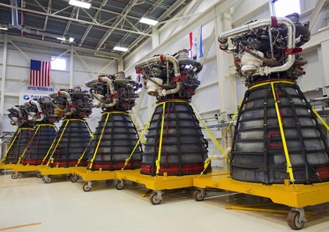
The follow-on to this historic event was the Space Shuttle Program and the Space Shuttle Main Engine. This Space Shuttle Main Engine (SSME) was a totally new engine that featured many innovative characteristics. The SSME was the most advanced liquid-fueled rocket engines ever designed, built, and fielded. They were manufactured by the Rocketdyne Division of Rockwell, located at Canoga Park, California.
Each Space Shuttle Orbiter had three SSME’s mounted on the aft fuselage in a triangular pattern. Each SSME was designed for 7.5 hours of operation over an average lifespan of 55 starts. SSME’s burned a combination of liquid oxygen (LOX) and liquid hydrogen (LH2) fed from the Space Shuttle External Tank (ET).
The SSME’s employed a staged combustion cycle, in which fuel was first partially circulated to critical components at high pressure and low temperature, then burned completely at high pressure and high temperature. This staged combustion of fuel allowed the SSME’s to produce thrust more efficiently than other rocket engines. A rapid burning of fuel in a staged burn gave SSME’s a combustion efficiency of about 99%. SSME thrust was variable, which was extremely important in Space Shuttle mission applications. This variable thrust ranged from 65% minimum to 109% maximum of its normal 100% rated power level at precise increments of 1% as needed.
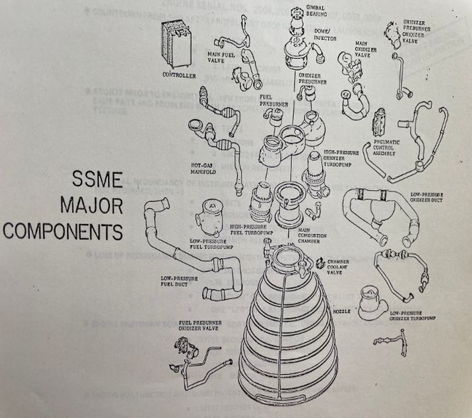
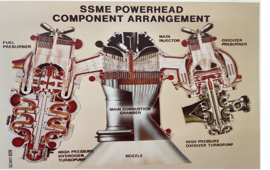
Figure 1 shows an exploded view of the major components of the SSME. Later in this write-up will be pictures and explanatory descriptions of the most significant of these components
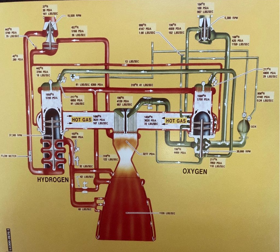
Figure 2 shows the propellant flow scheme from the External Tank (ET). RED indicates the fuel (liquid hydrogen, (LH2); the GREEN indicates the oxidizer (liquid oxygen, LO2).
Organization
Now to the Resident Management Office (RMO) at Rocketdyne, the Marshall Center’s propulsion partner for over six decades. The Resident Management Office at Rocketdyne was implemented during the Saturn program.
The Resident Management Office (RMO) concept originated with Dr. Eberhard Rees, Deputy Director under Dr. von Braun, as an on-site monitoring system of major contractor’s activities and progress during the Saturn Apollo program. Dr. Rees explained the process to the contractors: “In other words, you can expect our team to be in your ‘knickers’.” The MSFC Program Offices had representatives in major contractor plants that operated as a “mirror image” of the project managers at MSFC in Huntsville. The principle was to have multiple skills representing the variety of organizational skills at MSFC, but be physically located in the contractor’s plant. Thus, it was basically a mini-Marshall Space Flight Center, while only working on a single major contract.
The SSME was recognized and accepted as a huge, demanding, and extremely critical element of the Space Shuttle program. (The second most critical element was the Insulating Tile System on the under-side of the Shuttle Orbiter, a program pursued by Johnson Space Center (JSC), Houston.
In fact, the SSME was generally accepted as “the most challenging engineering system of the entire Shuttle Program” and was listed as a “critical path” item. Consequently, the SSME received considerable attention and continuous oversight at the highest levels of NASA management.
Each independent Laboratory at MSFC would determine its need to have an on-site staff person, determine the qualifications necessary to fill the position, select its representative, and ultimately assign that person to the contractor’s plant for a negotiable period of time. Obviously, the chosen individual must have demonstrated characteristics of self-starter, integrity, stability, communication skills, strong engineering, management skills, good and balanced judgment, steady inter-personal skills, and be a solid team player.
Rocketdyne was a strong contractor who had a solid record of outstanding performance and on-time delivery of engines with 100 % flight success for multiple flight programs. MSFC’s expertise in the propulsion discipline, however, recognized the complexity of this new engine and the magnitude of the tasks associated with its development. They understood this engine was pushing the engineering envelope to the brink of man’s knowledge and experience. Rocketdyne and MSFC accepted the challenge!
By 1974 the fundamental design of this complex engine was complete; individual critical components were being manufactured for testing.
Co-operative Staffing
After considerable review, MSFC management made the decision that increased participation by MSFC personnel should be implemented in the Rocketdyne Resident Management Office. Accordingly, this decision was implemented in the Fall of 1974. The RMO resultant staffing follows:
Jim Splawn, Resident Manager, SSME Project Office
Ray Tjulander, Deputy Manager
Ann Bowden, Secretary
Lillian Bright, Secretary
Bob Swaim, Materials Laboratory
Jerry Kidd, Propulsion & Vehicle Engineering Laboratory, Turbo-machinery
Bob Wagner, Propulsion and Vehicle Engineering Laboratory, Combustion Devices
Jack Weil, Propulsion & Vehicle Engineering Laboratory, Engine Systems
Denny Holweger, Facilities
Parker Counts, Quality Laboratory Manager
Benjamin Pagenkoff, Quality Engineer
Claude Buzbee, Mechanical Hardware
Charlie Pierce, Electrical Hardware
Jack Freedman, Finance
Ken Fisher, Contracting Officer
John Chaffee, Contracting Officer
At MSFC the Center Director was Dr. William R. Lucas. The SSME Program Manager was J. R. Thompson.
The disciplines mentioned above aligned with Rocketdyne’s major organizations and their respective products.
The Rocketdyne management staff was competent, committed, energetic, and demonstrated strong engineering capability. The comradery of the entire organization was contagious. Their mission was focused, the entire organization knew the mountain to success was steep, but believed deeply their ingenuity, stamina, and hard work would conquer that mountain.
Dom Sanchini was the Rocketdyne SSME Program Manager and ran a tight ship. His engineering and management skills produced a confidence that permeated their entire SSME staff. The two Program Managers, J.R. Thompson and Dom Sanchini, made a winning combination for the SSME program. Both were strong technically, hard-driving, yet showed compassion and deep appreciation and respect for all employees. For the operational posturing of the RMO staff, the environment established by these SSME Program Managers created a homogeneous atmosphere that permeated all organizations with full-and-open coordination without concern of reprisal. It was a real gift for the future of the SSME Program.
At MSFC, the SSME Project Office and its organization structure, and each Laboratory with its organization structure, were heavily involved in planning, scheduling, technical studies, documentation, solutions to operational problems, solutions to hardware test failures, briefings to higher management, and the list goes on and on. At Rocketdyne, very similar tasks were being pursued and accomplished. Consequently, and as you’d expect, there was significant interchange between MSFC personnel and Rocketdyne personnel on an hourly and daily basis, all of which was focused toward production and flight of a monstrous and complex rocket engine. Funding for the program was significant, but provided. Delivered cost for each of the SSME’s exceeded $40-million.
Operations
At Rocketdyne, two major organizational functions existed: design/engineering/manufacturing disciplines in Canoga Park; and the Santa Susana test facility, located in a mountainous area about 25-miles northwest of the Canoga facility.
The manufacturing shops operated 24-7 on high precision equipment, and produced flight-worthy components and sub-systems for development/verification testing and ultimate flight usage. The production equipment and tools were high quality which could produce hardware with very tight dimensions / tolerances for pieced-parts and end- product. The machinists and assemblers were highly skilled and committed, because they, individually, understood the ultimate mission of their workmanship. They had top-notch equipment, pride in their trade, and produced a high-performing product.
Subcontractors were utilized to the fullest for specialty hardware (i.e.: turbine blades, bearings, hydraulic actuators, etc.).
The Santa Susana Field Laboratory (SSFL), associated with Rocketdyne, is a complex of industrial research, development and test facilities, located on a 2,668-acres in an unincorporated area of Ventura County between Simi Valley and Los Angeles.
The continuous test program was the real proving ground for the final configuration and operational SSME. Along the way and as planned, much component hardware was destroyed in test as life-threshold was determined for all piece parts contained within the assemblies. The strategic location of multiple sensors (temperature, pressure, flow rate, strain gauges, etc.) both internally and externally, provided critical data for engineering analysis. After a test failure, this iterative process would be followed: redesign was based on instrumentation data that showed how, why, and where the failure initiated, upgraded/revised new hardware would be fabricated, hot-fire tested again – – repeat, and repeat again, until success was achieved. This evolved process was fine-tuned with the successes of the Redstone, Delta, Jupiter, Atlas, and the Saturn family.
Test hardware would be transported to Santa Susana where several test stands accommodated hot-fire testing of turbo-machinery, combustion devices, and limited full engine tests. Major full-up engine hot fire tests would be conducted at National Space Technology Laboratories (NSTL) in Bay St. Louis, Miss. The components produced by this testing process resulted in minimum loss of a complete engine during test firing at operating conditions. Testing was key to ultimate success!
SSME Components with Limited Description
For those who are unfamiliar with rocket engines, perhaps some orientation would be beneficial. I’ll not go into details here, but will attempt to give some insight into generalities, along with pictures.
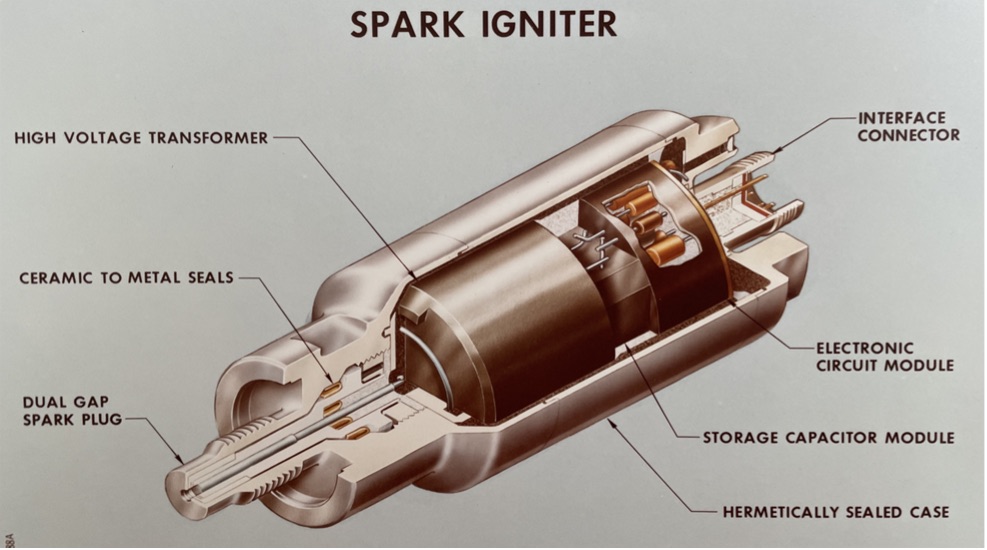
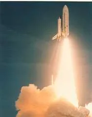
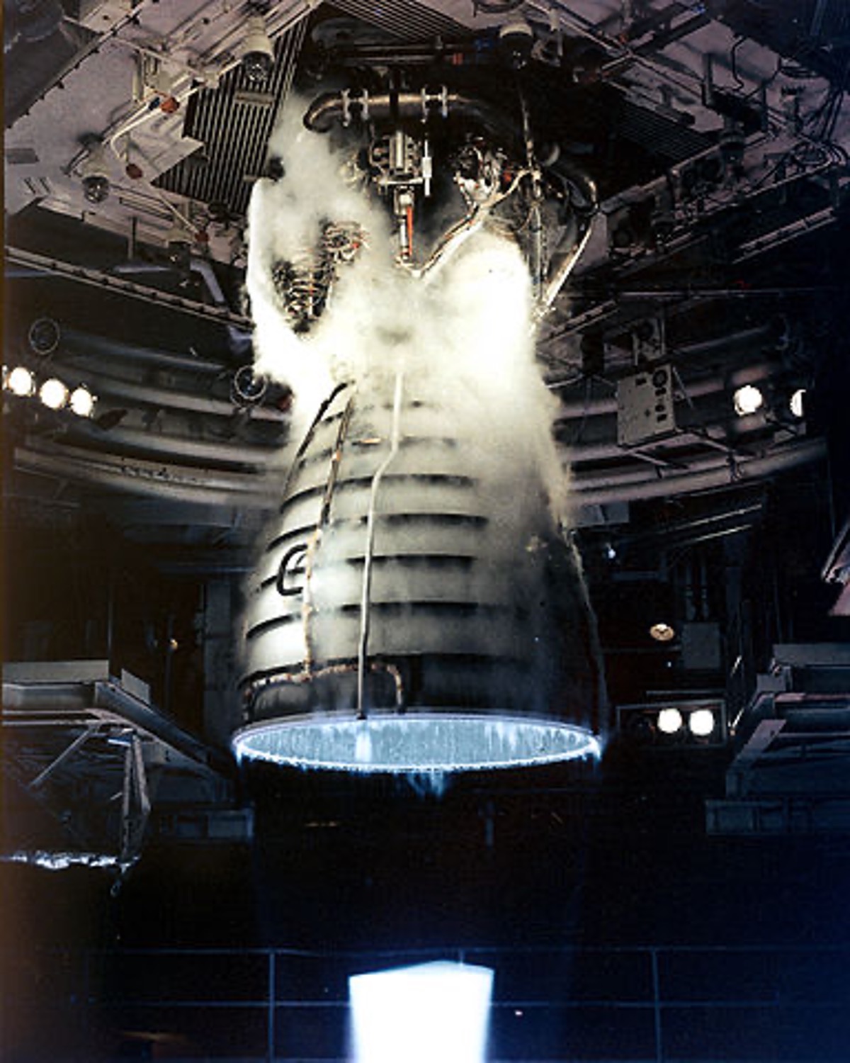
The SSME ignition process begins upon the command from the Orbiter to open both fuel (LH2) and oxidizer (LO2) valves. The Spark Igniter completes the ignition process for all three engines. The hold-down arms are active for 3-4 seconds while the on-board computer determines launch criteria conditions on each of the three SSME’s have been met (safety and power level). The Solid Rocket Boosters (SRB) are then ignited. Once the SRB’s are ignited, it is sometimes joking said: “you’re now going somewhere”!!!! (Note: To our naked eyes as observers, the “blue” triangle seen in the nozzle exhaust indicates hypersonic flow has been reached, a launch criterion. Further note, since hydrogen and oxygen elements combine to make water, the SSME exhaust is simply a mist of hot water.)
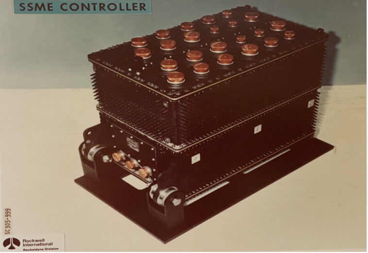
The checkout, start, in-flight operation, and shutdown of the SSME’s are managed by dual redundant 16-bit digital computers and their input and output electronics. A controller is shock-mounted on each engine. The controller interfaces with the hydraulic actuators and their position feedback mechanisms, spark ignitors, solenoids, and sensors to provide closed-loop control of the thrust and propellant mixture ratio, while monitoring the performance of critical engine performance. These monitoring and control tasks are repeated every 20 milliseconds (50 times per second). If any parameters are exceeded, the controller will perform a safe shutdown.
In addition to controlling the engine, the controller performs self-tests and switches to the backup computer channel and its associated electronics in the event of a failure.
The controller is packaged on a sealed, pressurized chassis, with heat transfer through pin fins as part of the main chassis.
The software is an online, real-time, process control program. The program will process the inputs from the control devices (sensors, solenoids, actuators, vehicle commands, etc.) while providing test/checkout and monitoring capabilities. The controller size is 14”x 18”x 24” and weighs 213 lbs.
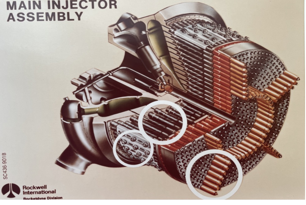
The Main Injector performs the vital function of finally mixing all the liquid oxygen and liquid hydrogen together as thoroughly and uniformly as possible to produce efficient combustion.
An intricately fabricated component, the main injector consists of a thrust cone, an oxidizer supply manifold, two fuel cavities, 600 injection elements, and an ignition unit. The thrust cone transmits the total thrust of the engine through the gimbal bearing to the Orbiter vehicle. The oxidizer supply manifold receives oxygen from the high pressure turbopump and distributes it evenly to the 600 injector elements. One of the two fuel cavities supplies fuel-rich hot gases to run the high-pressure turbines. The other fuel cavity supplies gaseous hydrogen from the hot gas manifold cooling circuit.
The 600 injector elements have an outer fuel shroud that surrounds a central oxidizer stream. The propellants are thoroughly mixed as they are introduced into the main combustion zone for burning at approximately 6,000 ℉.
The Main Injector is welded into the Powerhead and feeds into the Main Combustion Chamber.
The Main Combustion Chamber (MCC) is a two-walled cylinder between the Main Injector and the Nozzle. Its primary function is to receive the mixed propellants from the main injector, accelerate the hot combustion gases to sonic velocity through the throat area (typical hour-glass configuration), and expand them supersonically through the nozzle.
The expansion contour accelerates the combustion gases to the 5-to-1 expansion ratio with minimum energy loss.
The MCC consists of a coolant liner, a high-strength structural jacket, and two actuator struts, used to gimbal the engines as needed during flight.
The MCC operating pressure is approximately 3,000 psi.
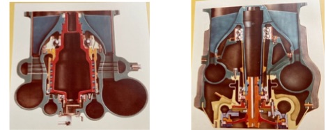
Turbopumps
The “rotating machinery family” consists of the following:
- Low pressure LH2 turbopump (LPFTP)
- High pressure LH2 turbopump (HPFTP)
- Low pressure LOX turbopump (LPOTP)
- High pressure LOX turbopump (HPOTP)
Turbo-machinery was the most complex to fabricate and most difficult to fine-tune to flight conditions because of high internal pressure, rotating parts, temperature, and extremely tight clearances, all of which varied during the operational test evaluations, and, ultimately, flight challenges. All four of the pumps are line replaceable units (LRU). The primary function of the low pressure pumps is to assure sufficient flow and pressure of liquids to prevent cavitation at the high pressure pumps. Operating conditions follow.
| LPFTP | LPOTP | |
| Pump inlet flowrate | 161 lb/sec | 969 lb/sec |
| Pump inlet pressure | 30 psia | 100 Pump |
| Pump discharge pressure | 283 psia | 431 psia |
| Pump efficiency | .679 | .615 |
| Turbine flowrate | 32 lb/sec | 181 lb/sec |
| Turbine inlet temp | (-) 460 °F | (-)192 °F |
| Turbine efficiency | .530 | .644 |
| Turbine speed | 16,249 rpm | 5,252 rpm |
| 5,252 rpm | 3,536 hp | 1,919 hp |
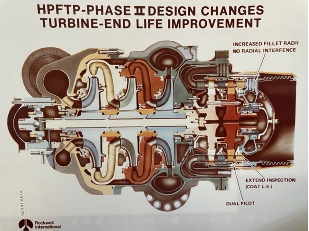
The high pressure fuel pump is a three-stage centrifugal pump driven directly by a two stage turbine. Fuel flows, in series, through the three impellers from pump inlet to pump outlet. Two double sets of ball bearings support the rotating assembly. A thrust bearing at the pump end of the rotating assembly provides axial rotor control during start up and shutdown.
Pump inlet flowrate: 162 lb/sec
Pump inlet pressure: 214 psia
Pump discharge pressure: 7,037 psia
Pump efficiency: .757
Turbine flowrate: 164 lb/sec
Turbine inlet temp: 1,989 °F
Turbine efficiency: .780
Turbine speed: 37,076 rpm
Turbine horsepower: 77,142 hp
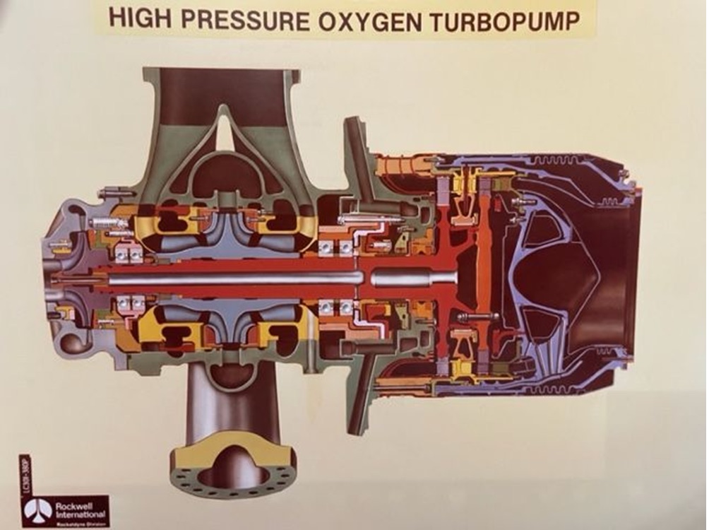
The high pressure oxidizer pump consists of a main pump, which provides liquid oxygen to the main injector, and a boost pump which supplies liquid oxygen to the preburners. The main pump has a single inlet and flow is split to a double-entry impeller with a common discharge. Two double sets of ball bearings support the rotor assembly and are cooled internally with liquid oxygen.
Pump inlet flowrate: 1,161 lb/sec
Pump inlet pressure: 390 psia
Pump discharge pressure: 4,793 psia
Pump efficiency: .678
Turbine flowrate: 71 lb/sec
Turbine inlet pressure: 5,570 psia
Turbine inlet temp: 1,499 °F
Turbine efficiency: .772
Turbine speed: 30,381 rpm
Turbine horsepower: 29,471 hp
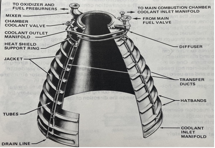
To provide maximum possible thrust efficiency, the Nozzle assembly allows continued expansion of the combustion gases coming from the main combustion chamber. It is designed for a 77-to-1 thrust chamber expansion ratio at high altitudes. This assembly is the largest component of the engine, measuring 8-ft diameter at the base. This assembly consists of a forward manifold subassembly and a stacked tube nozzle subassembly.
The forward subassembly provides attachment to the main combustion chamber and nozzle tube cooling circuits of LH2 prior to being circulated back to the mainstream fuel mixing in the main injector.
The stacked tube subassembly contains 1,080 tubes, tapered over the 8-ft length, and brazed together to form the desired contour. They are connected at the aft end to a coolant inlet manifold. Hydrogen flows through the tubes cooling the hot exhaust from the main combustion chamber. The tubes are enclosed in a structural jacket with reinforcing hatbands.
Resident Management Office (RMO)
The mission of the RMO was to actively monitor, on a daily basis, contractor performance against the many contractual requirements. The RMO responsibility included the overseeing of Rocketdyne performance for design, development, manufacturing, test, and delivery to meet flight requirements while keeping the MSFC SSME Program Office and support Laboratories informed of the progress toward program objectives. This responsibility was a huge undertaking and required acceptance of, and respect for, the government employees, individually and collectively, by the total Rocketdyne management staff and working level employees. This was a day-to-day continuous discipline situation.
Executive level managers, Thompson and Sanchini, obviously established the initial environment and expectations, but it was the daily personal discipline, demonstrated professionalism, and inherent integrity that yielded the critical relationships. This relationship could be lost in one day or it could be nurtured every day, on both sides of the equation. The key was stating the facts, accurately, fairly, honestly, and straight-forward. The balance of praise and shortcomings had to be handled carefully and in good taste.
Fortunately, the MSFC staff and the Rocketdyne staff, top to bottom, understood the difficult and critical tasks and conducted themselves accordingly. Forgiveness without individual blame, and praise for the team accomplishments, were great to witness. Don’t misunderstand; there were many, many times when significant, very significant problems occurred, and many disheartening hardware failures during test operations, but the joint teams tightened their belts, worked the situation, and pressed forward. This relationship made the MSFC/Rocketdyne working environment fun, but pressure packed, rewarding but with a few scars.
The individual staff members in the RMO owed their home organization at MSFC daily feedback on the progress or problems for their particular field of specialty. Frequently the home organization would send to California a traveler, with specific skills matching the problem area, to work with the Rocketdyne specialist. So, the RMO staff had to really understand the problem, articulate the situation clearly, and request MSFC assistance. Once on-site, the RMO staff would work continuously with the traveler and the assigned special team for understanding the process of correcting the problem while simultaneously gaining a good background for later follow-up. This scenario is a typical example all RMO staff would follow for similar situations.
Each RMO person was responsible for making continuous contact with his assigned Rocketdyne counterpart.
Each workday at 7:00 a.m. Rocketdyne held a ‘stand-up meeting’ in the “war room,” a large conference room with no tables or chairs, just status charts covering every wall where each organizational manager (Engineering, Turbo-machinery, Combustion Devices, Manufacturing, Quality, Engine Assembly, Test, etc.) would brief their progress of yesterday, the needs of today, and forecast for tomorrow. It was a significant communication tool as each could see the interplay between disciplines and how each was dependent on progress of others. When a problem was evident, those involved worked that situation immediately following the meeting. Our RMO staff attended these stand-up meetings for monitoring progress and understanding problem areas. With this data and if appropriate, communications with their Huntsville organizations were conducted to initiate support work on the problem as well.
SSME Longevity
The Space Shuttle Program covered a period of 30-years, 1981 to 2011. Five (5) Orbiters flew 135 missions during this period. With these 135 missions and three (3) engines powering the Orbiter, a total of 405 exposures existed. With each engine running for approximately 8-minutes, that converts to 3,240 minutes or 54 hours. For an engine that has approximately 4,000 piece-parts and a rugged environment of operation, that’s superb design and almost unbelievable workmanship! Cheers!!! There was never an engine failure!
The Orbiter’s payload bay weight limit was 25,000 lbs and was utilized to carry a wide variety of space hardware: telescopes, public service satellites, classified satellites, numerous technology advancement projects, medical research, etc.; all precious and expensive cargo. Greater than 40 missions were dedicated to building and activating the International Space Station, ISS, for continuous manned occupancy. Needless to say, a safe, reliable, and proven propulsion system was required. SSME met the demanding need!
Future Usage of Basic SSME
As normal and expected, the basic SSME has been continuously upgraded to meet the ever-increasing demands of launch power for new programs. The basic and core configuration of the SSME, however, remains within its fundamental design and operational configuration.
NASA’s next challenge: Artemis. The launch power system will again utilize both liquid and solid propulsion, both of which have met upgrade demands. On the liquid side, the core SSME has been renamed: RS-27, and will continue to use liquid hydrogen and liquid oxygen. (On the solid side, it has seen upgrades as well.)
So, back to the Moon … and on to MARS!!!! Buckle your seat-belt for a meaningful and successful ride!!
SSME / RS-27 is on the move!
SSME Data Sheet
The following Data Sheet provides insight into some of the characteristics and operating parameters for the curious-minded.
SSME – – Rocketdyne – – 1974
- Length: 14 feet; Diameter: 7 feet, 6 inches
- Design, Development, Test (Santa Susana Mountains)
- History – – every manned flight powered by RKD engines
- Employees – – 4,000 in ’60s to l0,000 in the ‘70s
- Extremely capable & competent company
SSME: Early Milestones
1970 – Design details made public
1971 – $442M contract award from NASA / MSFC: Design, Development, Launch; the most advanced rocket engine in U.S. history
1973/4 – Began component tests @ Santa Susana (upgraded test stands for SSME hardware use)
1975 – First delivery of SSME to NASA for exploratory development tests at NSTL, in Mississippi
SSME Major Systems
Three (3) major grouping of components: Combustion Devices; Turbomachinery; Controls
Snap-shot of SSME Capabilities
- Variable thrust (65% to 109%); 8.5 minutes total burn time
- Cryogenic propellants (LH2, LOX)
- 6 to 1 mixture ration (LOX to LH2 by weight)
- 470,000 lbs. thrust, each engine
- Gimbal (pitch, yaw, roll)
- Controller/computer (mounted on engine)
- Minimum Life (Contractual): 7.5 hrs. / 55 starts
- Weight: 6,600 lbs.
Engine System
- LH2 & LOX in External Tank (ET); cryogenic liquids: LH2 (-)423°F; LOX (-)297°F; 383,000 gal LH2; 143,000 gal LOX
- Propellant Feed-lines (ET to SSME’s): 17″ dia.; LOX flow 17,000 gal/min.; LH2 flow 45,000 gal/min
- Pre-chill each engine, before and during flight, via circulation of LH2 propellant (to increased strength of materials); then circulate propellants back into flow stream for ignition
- Each SSME has greater than 4,000 individual working piece-parts
- Each SSME was at the very edge of technology and engineering capability, Design, Manufacturing, and operational
Combustion Devices
- Ignition System: main injectors, pre-burners, MCC (Main Combustion Chamber), Nozzle assembly
- Combustion Start: 3-ignition units (2-preburners & MCC); 2-spark ignitors
- Main Combustion Chamber (MCC): igniter unit; 600 injector elements, operates @ 6,000°F, 3,000 psi
- Nozzle: allows expansion of combustion gases, 77 to 1 expansion ratio, wall temp ~ 880°F, 1,080 tubes, brazed, aft manifold 10′ x 8′
- Hot Gas Manifold: structural backbone of engine (MCC with turbopumps on opposing sides)
- Gimbal Bearing: mechanical interface w/Orbiter, transmits thrust load of engine to superstructure
Turbomachinery
- Low Pressure Fuel Turbopump (LPFTP) : 2-stage turbine … raises pressure of LH2 flow to HPFTP (prevent cavitation) – turbine driven by LH2 from ET: flow rate 147 lb/sec – 15,400 rpm – 3,000 hp – – no ignition
- High Pressure Fuel Turbopump (HPFTP): Preburner ignites gases that powers the 2-stage turbine which drives the 3-stage centrifugal pump – – operates at 35,000 rpm – – 6,200 psi – – develops 63,300 hp – – no ignition
- Low Pressure Oxidizer Turbopump (LPOTP): powered by LOX flow from ET at 900#/sec – 5,000 rpm – -1,600 hp – no ignition
- High Pressure Oxidizer Turbopump (HPOTP): powered by hot gases from LPOTP – – operates at 28,000 rpm – – 5,200 psi, flow rate, 1,100 #/sec – – develops 29,000 hp – – no ignition
Controls
Valves & Ducts: 5-ea: located at 2-ea preburners, 1-main LH2 line, – – 1-main LOX line, – – 1- MCC
Controller /Computer
- Dimensions: 14″ X 18″ X 24″
- Weight”: 213 lbs
- Engine mounted: vibration isolation mounts
- Dual redundancy, 16-bit digital computer
- Divided into 5 subsystems
- Software is an on-line, real-time processing
- Continuous monitor of engine health
- Issues commands from ‘start’ to ‘shutdown’, guidance, navigation, thrust level, etc. 5O times / sec
- Issues commands from ‘start’ to ‘shutdown’, guidance, navigation, thrust level, etc. 5O times / sec
Design Comparison
| Saturn V, F-1 Engine | Design Comparison | Space Shuttle, SSME |
| 1,522K | Thrust | 512K |
| 955 psi | Chamber Pressure | 3,240 psi |
| 1 | Engine Starts | 55 |
| 2,250 | Operating Seconds | 27,000 |
| 18,500 | Weight (lbs) | 6,600 |
Some Gee-Whiz Facts
- The External Tank holds 500,000 gallons of propellant.
- The combined pumping capacity of all three SSME turbopumps could drain an average sized swimming pools in 28-seconds.
- The 3-ea SSME’s at their combined full power produce an output of 37-million horsepower; equivalent to the output of 13 Hoover Dams.
- The Main Combustion Chamber reaches 6,000°F – – hotter than the boiling point of iron.
Engine Certification
The SSME contract, a $442M contract signed in 1972, contained a requirement that 65,000 seconds of cumulative single engine testing be achieved prior to first manned orbital flight.
The SSME development test phase began in March 1973 on multiple engine components (ignition systems, preburners, thrust chamber, etc.) at the Santa Susana Test Facility (SSFL) in the vicinity of the Rocketdyne manufacturing plant.
In 1975 the first SSME engine was shipped to Mississippi’s NASA Space Test Lab (NSTL) for full engine testing.
Operations
The Space Shuttle was conceived, designed, and built to be the workhorse for populating and working in space, a pivotal role in humanity’s expansion into space. The cargo bay of the Orbiter was equipped to launch satellites, huge telescopes (Hubble, James Webb, Chandra X-Ray Observatory, etc.). In addition, this platform provided opportunities for flight crews to continue and advance their skill capabilities of handling large structures in preparation for the assembly of the forthcoming ISS. The lessons learned by the flight crew for handling and managing large structures in weightlessness began in the Neutral Buoyancy Simulator at MSFC in the 70’s. And it all starts at “Engine Ignition” of the SSME’s!!
Reflections
The opportunity and experience of the Resident Management Office for this writer was significant and rewarding. The huge technical task was humbling, but the people at MSFC and Rocketdyne demonstrated the will, the skill, the confidence, and the professionalism to conquer the challenge. Together, we created a magnificent and endurable machine!
The following is a partial list of key MSFC personnel that served as my/our mentors during my assignment at the RMO at Rocketdyne, each with critical skills and unique personalities, and all great friends. I’m indebted to all: J. R. Thompson, Larry Wear, Brenda Sutherland, Joe Lombardo, Gerald Smith, Zack Thompson, John McCarty, Otto Goetz, Len Worlund, George Hopson, Bob Schwinghamer, Jerry Thomson, Norm Schlemmer, Bob Ryan, Walt Mitchell, Ed Mintz, Carlyle Smith and Bob Morris.
The following is a partial list of key Rocketdyne personnel that served as my/our mentors during my assignment at the RMO at Rocketdyne, each with critical skills and personalities and all great friends. I’m indebted to all: Dom Sanchini, Jerry Johnson, Ted Benham, Ed Larson, Bob Crain, Willie Wilheim, Paul Fuller, Bob Biggs, Erv Eberle, Byron Wood, Jim Hale, Frank Lary, Joe Stangeland, Matt Ek and Don Mikuni.
Accolades
For this writer, what a ride!! The SSME was an angry tiger with sharp teeth and claws, unforgiving, but it was subdued and the end product was a beautiful sight to behold, each and every time the SSME igniters began the ride.
The people, oh my, the people are all professionals, committed, individually and collectively, just the kind that will not quit until the big job is successfully complete. The machinists, welders, assemblers, engineers, scientists, computer geeks, technicians, test crews, inspectors, shippers, secretaries, managers, the family team members that understood and provided encouragement …. and the list goes on. Teamwork is so sweet … NASA and Contractor.
Personally, I have been extremely blessed, far beyond my meager skill and talent by the friendship and guidance by so many throughout my lifetime. Sincere THANKS to all!!